The ability of a Bumotec machining centre to undertake micro-machining was recently demonstrated by engineers at the University of Sheffield Advanced Manufacturing Research Centre (AMRC), who used the Swiss-made mill-turn machine to reproduce a series of tiny portraits of Queen Elizabeth II (in brass) — one of them just 1.4mm wide (the intricate detail of Her Majesty’s head on the latter can only be seen clearly through a powerful microscope).
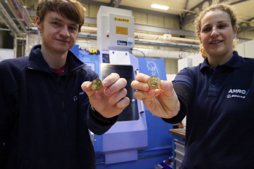
This project was undertaken by engineers Emma Parkin and Joe Thickett, who wanted to create the miniature artwork to demonstrate the AMRC Machining Group’s capabilities, help to bolster industry knowledge on micro-machining and help UK firms to win business.
Supplied by Birmingham-based Starrag UK Ltd (
www.starrag.com), the Bumotec s191 — one of eight Starrag machines at the AMRC and its sister centre, the Nuclear AMRC — was used to produce four highly detailed Queen’s heads with diameters of 11.2, 7, 2.8 and 1.4mm — on a single circular piece of brass 25mm in diameter.
The two engineers used Sandvik micro end mills to achieve the basic shape of the design, before switching to tiny ball-nose cutters — the smallest just 0.2mm in diameter — for the detailed contouring.
Ms Parkin said: “We chose Her Majesty as a portrait, because we wanted to do something similar to a coin, as it is relatable. People generally know the size of a coin, so being able to scale it down in size yet still keep the Queen’s face means there is a ‘wow’ factor.
“We wanted to show our partners and wider industry what is achievable; that we can work to an accuracy of 0.001mm on workpieces as small as 1.5mm and maintain detail.
“To ‘capture’ Her Majesty’s face, we scanned a real coin with a 3-D microscope that is normally used for detecting surface roughness. It took a series of pictures, which were ‘layered up’ to create a 3-D image that was subsequently converted into an STL file format.
“That was then uploaded into Siemens NX 12 CAD for generating the machining program. We started cutting at 4mm depths to remove the bulk of the material, then went down in size; when we got to the finishing operations, we were applying micron ‘step-overs’.”