Cambridge-based NCG CAM Solutions Ltd has released NCG CAM v17.0. This has a ‘new look’ and a modern user interface; a demonstration version is available to download.
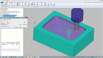
The NCG CAM v17 user interface has a Ribbon Design, as Ribbons are the ‘modern way’ to help users find, understand and use commands efficiently.
The command bar organises the program’s features into a series of tabs at the top of a window, making it easier to discover new features and functions (
www.ncgcam.com/demo-download).
The new Dynamic Material Removal feature has been added alongside the existing cutter animation function.
It can indicate the direction of milling (climb or conventional) — and identify any gouges or collisions.
This capability enables better visualisation and verification of the material stock removal produced by the calculated tool-path.
Other new features for drilling — Hole Shape Database and Compound Drilling Cycles — further automate the generation of drilling cycles.
It is now possible to create a database of hole shapes and to have the Drilling Data Folders searched for those hole shapes — and several cycles can be grouped together as compound cycles, to apply them to specific hole shapes.
The Compound Drilling Cycle can also be applied to holes of different directions (tool axis), so that holes with different directions but the same hole shape can be programmed in one step.
Meanwhile, when Cutter Compensation is applied (left or right) to the Along Curve Passes machining routine, after adjusting for the compensation, the proposed cutter path centre line is now displayed as a dotted line, giving visual confirmation of the actual tool-path offset.
Among many other enhancements in this latest version is an extension of the Co-ordinate System entity to include the axis rotation information (users can create a points folder containing key reference points and defining the orientation).
Where multiple parts are imported, this feature will reduce the time to relocate them to a common Co-ordinate System.
Another new feature enables users to project a 2-D boundary onto a surface; this helps to create additional containment boundaries and is particularly useful when undertaking 3+2-axis machining.
There have also been improvements to the internal graphics library and rest finishing (this now supports ‘toroidal target cutters’).
Soon to be available is a function that will allow users to create a surface patch from two 3-D curves (if the curves have coincident start points, then the surface created would resemble a triangular patch; if the two curves are spaced apart, this would create a rectangular patch).