A steam train that has not been seen since the 1960s is being rebuilt by a group of engineering enthusiasts with the help of industrial laser scanning experts at the
University of Sheffield Advanced Manufacturing Research Centre (AMRC), who ‘got the measure’ of a mysterious discrepancy between the original drawings and the actual locomotive.
The Standard Steam Locomotive Company (SSLC) is aiming to recreate, operate and maintain this British Railways’ Standard Class 6 ‘Clan’ using the original 1950s design drawings and 21st century engineering.
The AMRC was involved in a major frame alignment measuring exercise for the project after a review of the ‘build inventory’ showed critical gaps in documentation for some of the key parts relating to the locomotive’s frames.
Phil Yates, a chartered engineer at the AMRC and member of the volunteer group whose headquarters are located at the Sheffield-based engineering firm CTL Seal Ltd in Sheffield, said missing documentation is thought to be due to the fact that the locomotive was designed in Derby and constructed (between 1951 and 1954) in Crewe — some 50 miles apart.
“In some ways, the drawings were a wish of intent. By the time they got to the shopfloor some 50 miles away, if there was a mistake, the fitters would correct it and make a note of it in a little black book, which more often than not never made it back to the drawing office for the error to be corrected on the original drawings.
“Moreover, when we converted the original 1950s British Rail drawings into CAD models, it was apparent that the way the fastener hole patterns had been datumed on the frame and the frame extensions was not identical. The maximum error on the CAD components was 1.6mm because either the person who did the drawing of the frame or the person who did the drawing of the frame extensions got something wrong.”
As both the frames and their extensions had been laser profiled by separate companies to the original drawing, it was assumed that these errors existed in the parts. To ascertain the size of the error, the frames and frame extensions, which were stored in separate locations, had to be measured.
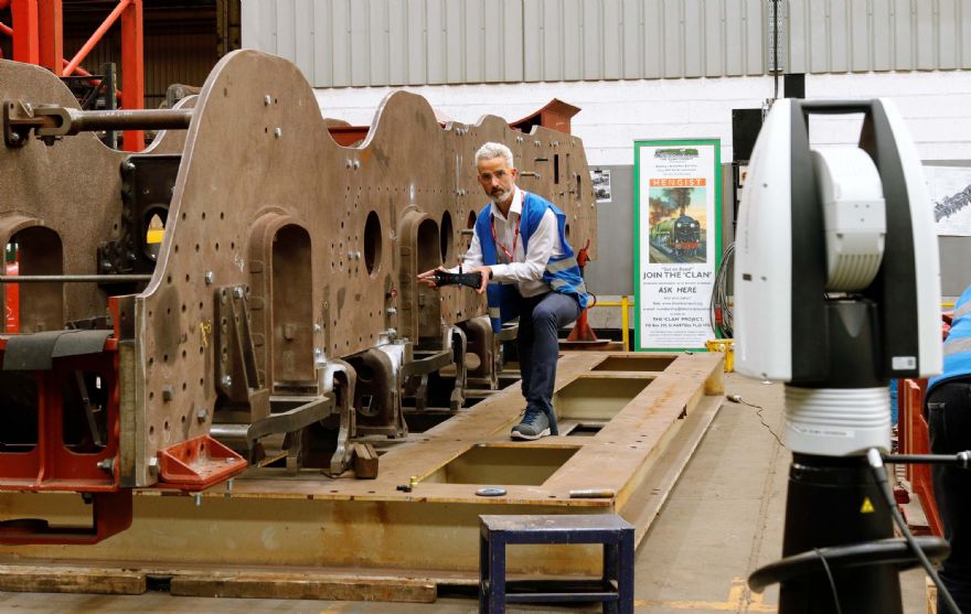
To measure the frame extensions at East Lancashire Railway works, Dr Yates used a Leica Absolute Tracker AT402 laser scanner combined with a Leica B-Probe from Hexagon Manufacturing Intelligence division.
To confirm the frame assembly dimensions Dr Yates and SSLC used a Leica Laser Tracker ATS600, a new type of targetless scanning tracker that seamlessly combines scanning with tactile measurements. It has a scanning range from 1 to 60m and a reflector range from 1 to 80m.